weChook Racing: Electric 3Galoo Build Log – Lessons Learnt

In case you haven’t worked out from the lack of us being at races so far this year, 3galoo has not been progressing smoothly.

We’ve had numerous problems with the wheels and driveshafts at the rear of the car, and I thought it’d be a good idea to record what we’ve learnt so that other teams out there don’t repeat the same mistakes.

Without further ado:

Bearing Fits

We had the hubs and bearing spacers for the wheels machined by a local engineering shop. Having checked my drawings with one of the technical specialists at work, I had good confidence that the drawings were correct, and most importantly, correctly toleranced.

Sadly, the parts we received back were not up to scratch. The recesses within the hubs for the bearings were too small for us to fit the bearing, although not by an amount that we could measure with a set of calipers. It wasn’t until I sent the parts to my friendly technical specialist that we realised that they were less than 1/10th of a mm too small – this was enough to completely prevent us from fitting the bearing.

Foolishly, we wrecked one hub by trying to turn out the extra hundredths of a mm with our bench lathe which really was not up to the job – we went from not being able to fit the bearing, to it falling immediately back out.

This all put a massive damper on progress, and enthusiasm – as the first thing that we’ve not done ourselves, for it to go this poorly was a bit of an eye opener. We know for next time – make sure our tolerancing is documented properly, make sure the person doing the machining understands and agrees what is required of them, and if possible, get the bearings to them that you want to fit!

Shaft diameters

Our next problem was with the shaft that we bought to use as the rear axles. To our calipers, the shaft we bought was a constant 18mm diameter the whole way along, so we couldn’t understand why it would only fit part of the way through the holes that we needed it to, and why it slopped around at other points.

Again, a measurement with a higher resolution tool showed us that the shaft was definitely not a constant diameter along its entire length. We were advised to instead purchase Cold rolled bright mild steel, which has a much more consistent outer diameter, and has really reduced the amount of wobbliness at the back of the car.

From this we learnt how much difference an imperceptible change in diameter can make, and therefore the importance of using the right materials.

Tolerance Stack up

The design we came up with introduced a lot more ‘critical tolerances’ than it needed to, meaning that many dimensions on many parts needed to be machined perfectly for the design as a whole to work.

The redesign at the rear end used a shaft that we knew would fit well into the I/D of the bearing with no further work, reducing the number of ‘critical characteristics’ by two.

This approach of designing to minimise the ‘critical characteristics’ of any given part makes the entire system more robust, and easier to manufacture, which is a big win!

Hopefully this has been of some use to someone who’s looking at building their own car!

weChook Racing: Electric 3Galoo Build Log – Building the ‘mono-coffin’ continued

Success, a second blog post about actually building the car, perhaps we are on a roll….

Last night Matt and I got home from work and cracked on prepping our Divinycell panels for gluing. Matt cracked on with a file and some sand paper to neaten some of the edges that we would be bonding to. While he was doing this I got to work building a simple router planer machine.

We needed to be trim the floor pieces down from 20mm thickness to 15mm, and the front panel would need to be 10mm. We have tried in the past using a home made hot wire to cut the foam in large sections however, doing such wide panels results in the wire deflecting a lot inside the foam which means we often end up with a wave like pattern in our foam, not ideal for keeping a nice flat floor! The router planer would remove/destroy more material than the hot wire method, but this wouldn’t matter as we are only removing a small amount.


1462556595524IMG_20160506_1854581462551395507
Hopefully it is obvious how this machine works from the pictures above, it was very simple to make and would be a fantastic DT project in a school. The router sits in a rail which gives us our X axis slide. The Y slide is purely done by manually pushing the panels through the tool. Z axis is set by plunging the router down and setting it’s height stop in order to remove the desired amount of material. The important thing is to not push down on the router too much as it may flex the MDF frame and cause a deeper cut than you want. This unit didn’t take long to make and worked perfectly for our purpose.

Pushing the panel in from one end I then move the router across, removing 1 router bits worth of material per stroke. 10mins and ALOT of foam mess later (have a shop vac and dust mask to hand here!) and the panel is trimmed. A quick pass with some sandpaper and we have a panel that is thinner and ready for bonding to the rest of the chassis.

Now that the panels are the correct size and thickness Matt is able to throw them together as seen here. Next up, gluing the chassis together.

weChook Racing: Electric 3Galoo Build Log – Building the ‘mono-coffin’

Welcome to the ‘build log’ of Electric 3Galoo, Matt and I have always thought about showing the build process of one of our cars but a rushed build has always taken priority over documenting it. Perhaps that will happen this time as well….who knows, we will try to keep this updated as best we can!

One of the things we really liked about 2Galoo’s design was the use of a fibreglass reinforced foam driver cell. Some of the reasons we like this build method are:

  • Strong enough to bolt front and rear subframes to without additional framework
  • Immediately meets the requirements for keeping the driver safe in the event of a crash, without the need for bodywork providing any additional crash protection, this leaves our options open regarding a how we make our bodyshell
  • Lightweight
  • Cheap (the rohacell panels that made up the last car was free from a skip!), we got an incredible deal on the Divinycell we are using for this build
  • Easy! It really is, as long as you don’t mind the possible mess of epoxy resin the foam is easy to cut and shape to your desired form. You can then test and add to it as required to ensure things like your batteries fit in and your driver is comfy before then sealing the structure solid with fibreglass.

We are going to approach this build in a slightly different way. Build the entire drive cell first and fibreglass it then add our subframes and other components afterwards. It was very messy in the last build trying to glass in the steel subframes and we think we ended up with an overall weaker structure. This new method should allow us to add extra glass where needed to strengthen the areas where the most stress will be put in to the driver cell (harness mounts, subframes, etc). It will also mean we can unbolt things if we want to move them in later versions of the car. Realistically this design cannot get any smaller and still fit me in it so the rest of the car (bodywork primarily) will have to be built to this footprint.

Enough babble, on with some build!

IMG_20160505_193203[1]IMG_20160505_193137[1]IMG_20160505_193144[1]IMG_20160505_193102[1]

Matt uses the CAD drawings (yes we have CAD this time, thanks Solid Edge) to draw out the shapes we need on to some Divinycell H80 foam. In an ideal world we would get this cut by a laser/water jet cutter for absolute accuracy, but we don’t have one of those so we are making do! Once we have the shapes drawn I got to work with a jigsaw to cut out the shapes roughly to size. It doesn’t take long and the foam is great to cut by hand as well, perfect for schools I would think.

received_10154805025717598[1]received_10154805025462598[1]IMG_20160505_193112[1]IMG_20160505_193054[1]

While I cut the main shape out my girlfriend Jodie gets to work cutting the detailed lines using the bandsaw. I then finish off some of the more awkward cuts that my small bandsaw can’t quite get in to do. Once we were finished we had a pile of car shaped jig saw pieces. Overall this took around 2 hours with a few people working. Next job is to try and reduce the thickness (currently 20mm) or some of the panels, then glue them all together!

We have also really enjoyed reading the build blog found here http://greenpowereasybuild.blogspot.co.uk, some great ideas for construction and a valuable read to any teams thinking of scratch building a car.

weChook Racing: Electric Boogaloo/2Galoo gearing design

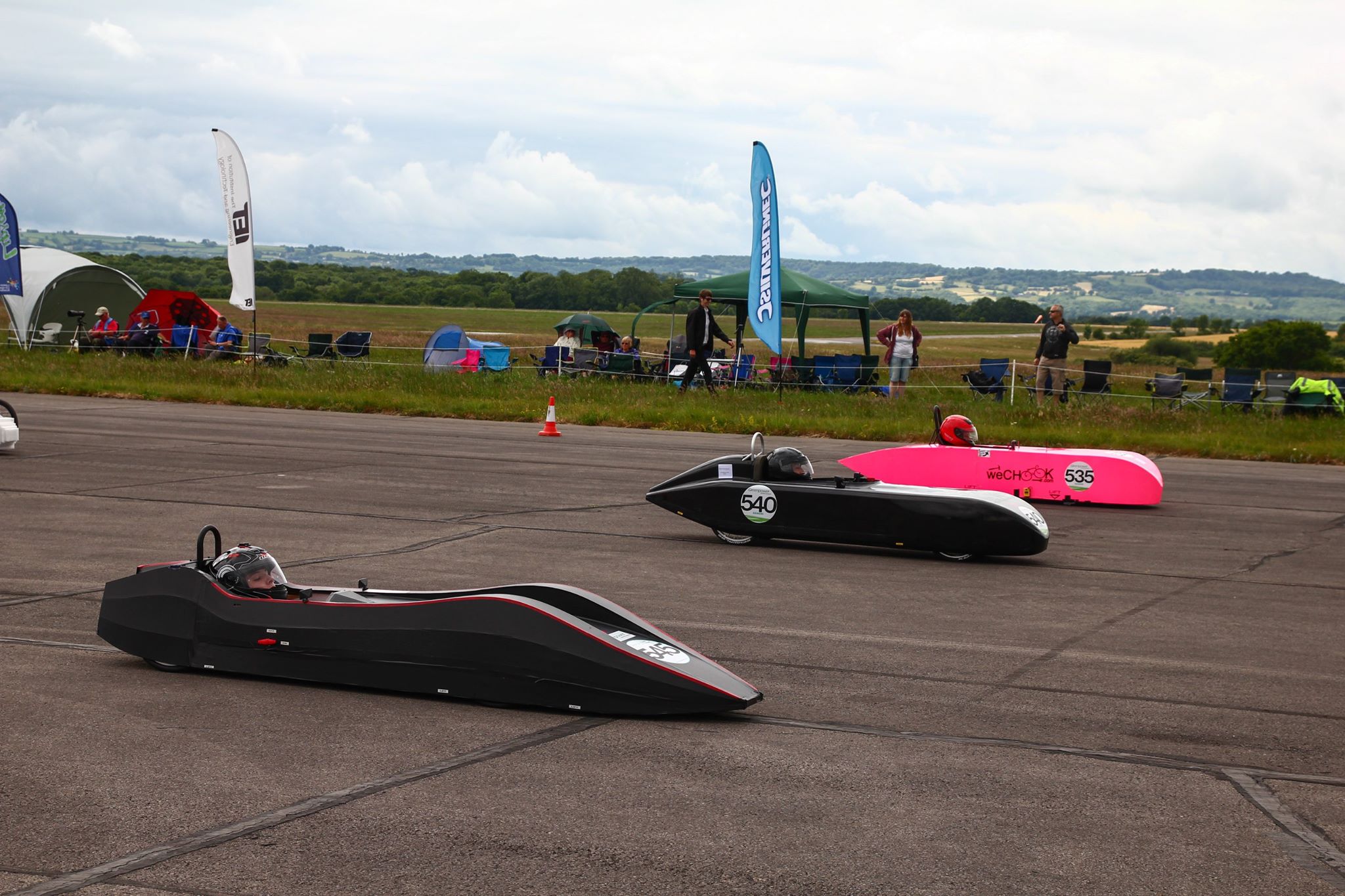
Every race we took the previous 2 cars to we had plenty of people crowding round our rear end to get a look at the gearing system we were using on the car, a system that was successful enough to make it between Boogaloo and 2Galoo almost completely unchanged. Due to slightly different wheel sizing offering up a different set of options for our next car it may not make the cut (design stages still in progress here!) but I thought I best take the opportunity to document the setup here for others to use hopefully with the same success.

Note, this post is by no means a plug for gearing your car, let’s not forget that plenty of fixed gear cars are in the top 10 in F24+! Clearly fixed gear cars can be done very very well (Rotary Racer and Jet to name just a few of our competitors).

DSC_0580DSC_0578DSC_0577DSC_0576

Another thing to remember is that geared systems add inefficiency in your drivetrain. This is primarily down to the chain having to curve round gears, each link having to rotate slightly causes wear on the chain and generates a small amount of heat. This is pretty much unavoidable in a green power car as you (almost) always have a chain drive, but imagine in a derailleur system how many bends the chain has to go round vs a single gear ratio system! More bends = more chain link rotations required = more heat generation = less efficiency. There is also the issue that the chain is not always running in a perfectly straight line, this not only wears the chain faster but also causes inefficiency. However, as with all good engineering, this is a compromise that the team has to consider, are these inefficiencies in your drivetrain compensated for by the more efficient running of your motor/batteries/vehicle system?

Why do we like having multiple gears on our cars? The main advantage to having driver selectable gearing the car (over having a single gear ratio that the team determines at the start of the session and has to stick with for the whole race) is the flexibility it offers. You use the gears the same way you would in a combustion engine car, to get the torque or RPM output at the wheels you require for the situation that you are in, while keeping the motor/engine in a sweet spot for torque/RPM out.

Now there is plenty of debate regarding race tactics (constant speed vs constant current draw that I am sure Matt will go in to in another post) but we still feel that gearing offers the flexibility to the driver to get the best out of the car in all situations and, gives the driver something else to do to keep them occupied. With our telemetry system feedback (eChook Nano boards coming soon!) we feel that the gearing offers us a chance to learn a lot about the different strategies a team can use, how you then choose the systems ‘sweet spot’ is then up to the team on the day.

The Gearing

When we built Boogaloo and 2Galoo we only had basic tools and no precision engineering equipment to speak of (lathes, pillar drills, milling machines). The result of this was that I wanted to use as many off the shelf bike parts as I could as it meant that we could guarantee that these would be made concentrically and we would end up with a gearing system that would hopefully be as efficient as possible.  (Unfortunately this does also mean that Matt hasn’t done any of his excellent Solid Edge CAD that I can post up in this blog post, but there will be more of that to come later)

Hopefully this blog post will help other teams who are wanting to build something similar to this design.

DSC_0575DSC_0573DSC_0572DSC_0571

The good bits about this design:

  • Easy to make with basic tools
  • Mostly off the shelf bike components, mostly cheap!
  • Very small gear ratio increments between gears (in our eyes this is perfect for a GP car), this is mostly thanks to gearing on one side of the lay shaft before then gearing again (maths bit to come!)

The bad bits:

  • 2 chains = more loses
  • More weight including the dreaded extra rotational mass
  • Lay shaft adds frictional loses
  • High chain speeds (~4x that seen on a push bike) on the derailleur side chain, though we have not had any issues with chain dropping for the whole 2015 season!

The use of a lay shaft in this system allows all of our gear ratios to end up very close together (see the ‘maths’ bit below), far more so than having put the gearing directly on the wheel end. It also allows us to use a derailleur the ‘correct’ way up while getting the advantages of a freewheeling hub (you can push the car backwards without worrying the chain will fall off!). If you look closely realistically you can see the rear end of a bike has been used, though the pedals/crankset have been replaced with the motor and the spokes/wheel have been replaced with the second chain to send drive to the driven wheel.

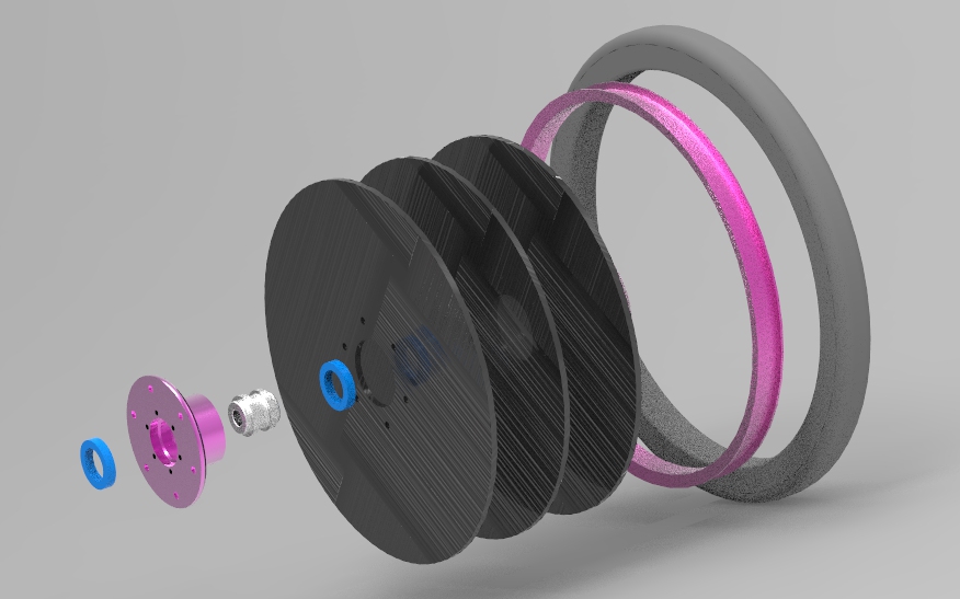
Parts of the system and tips on how we built them:

  1. The system starts at the motor output shaft. Here we have used a 10T gear that we managed to salvage from an old bicycle cassette I had lying around. It is important to remember that the chain on this side needs to be the correct ‘speed’ to match your cassette, in our case 9sp. By using an old cassette gear I know that it will be around the correct tooth width for 9sp. An old bicycle freehub is cut down to get the neccessary spline fitting to mesh with this gear which allows us to slide the gear off and put a different one on however, I am sure you can get away without this if you expect to change this gear size by simply welding the gear on to a coupler. There are 2 other larger gears shown which were a temporary (still going 1 season later!) measure to act as chain guides should the chain try and jump.  This spline fitting is then fitted to the motor shaft via a steel coupler that we already had in stock, the two parts are welded together. Once I had access to a small lathe this part was later machined in to what you see in these pictures, this was simply to improve our accuracy.
  2. A 9speed chain carrys power from the motor to the rear cassette, an off the shelf part that is mounted on to a disc braked mountain bike hub. The hub is the clever bit of this design. It gives the system a great way of achieving an idler shaft without the need to make your own bearing mounts etc. The freehub built in means that the ‘geared’ side of this setup doesn’t rotate when your car is freewheeling.  You can see the slotted piece of steel we used to mount the hub in as well as the conventional bike ‘skewer’ that is still used to clamp the hub in place. This allows you to easily tension the ‘fixed gear’ side of the gearing, putting the correct amount of tension in to the chain on the left side of the car, the derailleur takes up the slack on the right had side chain.
  3. Over the other side of the idler shaft the disc brake mount is used to fix a 20tooth ‘single speed’ gear to. These are cheap but are made of very hard steel, very hard to drill! It can be done at home but I had a friend with a decent drill setup drill 6 holes in this gear so it would mount to ths standard disc brake bolt pattern. http://www.chainreactioncycles.com/gusset-1-er-single-speed-sprocket/rp-prod17778
  4. A single speed chain carries the power to the driven wheel. Our wheels have disc brake compatible hubs which means we have another opportunity to use this to pass torque in using this simple 6 bolt pattern. We wanted to be able to use normal bicycle chainrings which bolt up to a 5 bolt pattern PCD, this would allow us to change chainrings later if we wanted to change our ratio set.  This part was a little hard for us to sort  but would be easy with the correct access to laser cutting/decent fabrication. We ended up using a spider made from aluminium (link below), this was not the neatest solution as we had to open out the centre diameter to fit our axel as well as drill our own 6bolt pattern on to it. http://www.ebay.co.uk/itm/REDLINE-110-mm-BCD-SPIDER-for-one-peice-cranks-BMX-old-school-/371147285617?hash=item566a1a2471
  5. Gears are selected with an indexed shimano shifter (9speed). Currently we preference having ‘thumb’ shifters MTB style but may try some other options in the new season. With this setup I highly recommend getting the best gear cables you can afford (Jagwire seems quite good) as the length of inner/outer cable you need to run is quite long. Keep kinks to a minimum in order to reduce the friction, otherwise you may have trouble selecting gear.

The maths bit

This is a great exercise to go through in schools and excitingly when you do have a gearing system with telemetry (eChook Nano boards coming soon!) you will actually be able to check your calculations using the wheel speed and motor speed sensors to measure a ratio of gearing between the two!

The facts:

  • Motor gear: 13tooth
  • Lay shaft gear cassette: 14,15, 16, 17, 18, 19, 21, 23, 25
  • Lay shaft fixed gear: 20tooth
  • Wheel gear: 34tooth

The formula for working out your gears (with a lay shaft) in this setup works like this:

Overall Ratio = (Current Selected Lay shaft Gear / Motor Gear) * (Wheel Gear / Lay shaft Fixed Gear)

For our setup above this gives us a great set of ratios for us in F24+ on our car. The ratios we end up with start at 1.83 (very high wheel speed per motor RPM, a good high speed gear)) and end at 3.27 (very  low wheel speed per motor RPM, a good pullaway and hill climbing gear), the difference between ratios is 0.13 for the single tooth steps on the chain ring and 0.26 for the 2 tooth steps. For our car this set of ratios offers a good range as well as resolution between gears.

We would suggest you have your team make a nice excel document with these calculations in (hopefully using our numbers you will get the same set of results we did!). Although these ratios work well with our car with our wheel sizes in F24+ they will not be optimum for other cars. An excel sheet will allow you to tweak things like the cassette you buy and the other gears in the setup in order to get the best result! It’s an exciting piece of maths to play around with and understand the impact that each gear has on your range (difference in ratio between top and bottom gear) and your resolution (differences between each gear you can select). Every gear in the system plays an important role in the result! You team probably has a good idea of the ratios that your car runs best at already from being on a fixed gear system, make sure these are included in your range of ratios available.

weChook Racing: 3galoo Design: Wheels

The first thing we decided upon for Electric 3galoo was a change to smaller diameter wheels – 16 inch rims down to 14 inch. The main reason we hadn’t done this previously were concerns over the cost and availability of tyres that fit this size rim, but after discussions with Matt from Renishaw (https://twitter.com/Hunter_Concepts) we decided to take the plunge.

The main advantages of smaller wheels are aerodynamic. The steering envelope is reduced, meaning the total width of the car can be reduced (or the same width can be maintained with less cambering of the front wheels), and the top surface of the car can be lower, reducing the total frontal area.

Plot showing estimated aerodynamic vs rolling drag for 2galoo

Plot showing estimated aerodynamic vs rolling drag for 2galoo

The con of smaller wheels is higher rolling resistance. Rough calculations say that at F24+ speeds, aerodynamic drag exceeds rolling drag by at least a factor of 4, so it shouldn’t be too hard to get a win in the trade off.

As well as reducing the diameter of the wheel, we wanted to make them narrower. The widest point on Electric 2galoo is at the centre of the rear wheel, at 560mm. As well as being well over the minimum track width of 500mm, having the widest point on the car so close to the back is aerodynamically very disadvantageous – we found it impossible to make a smooth curve for the bodywork that came back to point, as seen on Reprobation and Jet.

In order to reduce this width we needed to forego spokes, replacing them with solid carbon disks. We’d also have to replace the standard bike hubs we’d used on our previous cars with something a bit more bespoke.

Our original design (made before we’d actually got our hands on the rims we planned to use) is shown in exploded view below. We planned to fit some foam cored carbon sandwich panels inside the rim, with a hub bonded and bolted around them. We would have had the same wheel design at the front and back of the car – the front wheels would have been bolted through in a similar fashion to 2galoo, whilst the rear wheels would be attached to a brake disc holder to enable driving/braking torque to be transferred to them.

Initial flat wheel design

Initial flat wheel design

Once the rims arrived, we noticed a few problems with this design – the inside of the rim was angled, which would make it very difficult to get a good bonding surface between it and the carbon discs. The outer surface of the rim however was vertical,  making it a perfect bonding surface. This led to our second design iteration – instead of bolting the hub around the carbon discs, the discs would be attached around the hub.

Second flat wheel design iteration

Second flat wheel design iteration

This reduced the complexity of the hub, reduced the number of parts we’d have to turn, and increased the bonding surface area on the rim, hopefully resulting in a stronger final product (in fact, my calculations say that each bond should be able to support 865kg – slightly more than we’re planning for 3galoo to weigh). This still allowed us to keep the front and rear wheels identical – a big benefit when it comes to keeping spares.

If anyone would like a closer look, the drawings for the first hub is here: Hub and the second is here: NewHub

Next up, the chassis!

weChook Racing: 3galoo Design: What’s Different, What’s the Same?

As we came to the decision to build a new car for the 2016 season, the first question was ‘What do we keep the same, and what do we change from 2Galoo?’.

There was an easy answer for this when we started designing and building 2Galoo: Change everything! Boogaloo was huge, bendy, impossible to drive in the pit lane and slow. Only two things made it intact from our first to second cars – the layshaft gearing system, and the electrical system (and even that was directly carried over from C-XeVolution / Project-E).

Electric Boogaloo at its last event - vast compared to its competitors

Electric Boogaloo at its last event – vast compared to its competitors

So change everything we did! In order to reduce our aerodynamic profile we lowered the driver’s seating position, cambered the wheels and replaced the steering wheel with a lever – all in all reducing our frontal area by more than 30%. To increase stiffness we replaced the steel space frame / plywood construction with a tub made from Rohacell (with the added benefit of a ~4kg weight saving).The steering was redesigned from scratch, using trail rather than caster to maintain high speed stability, without the awful dry steering – it mostly went to plan apart from breaking at half the races 2galoo attended.

All in all, I’d say it worked! 2galoo competed in the second half of the 2015 season, achieving 2 podiums and finishing in 8th place in the final championship standings. Ahead of us were a car each from JLR and Renishaw, two cars from Silesian University (regular corporate challenge winners), Rotary Racer (many times F24 champion) and Jet (2013 and 2014 F24+ champion).

With that in mind, what next? Having analysed the competition (aka: poked around in the garages after everyone else went to bed at the International Final) we picked up on a few areas in which we were lagging behind the cars beating us:

  • Bodywork – In both form and surface quality 2galoo lagged far behind the cars that finished the season ahead of it.

  • Wheels – Most of the cars that were ahead of us had created a flat wheel in one way or another, meaning it wouldn’t have to be trued, and that the total width of the car could be reduced. Also, Renishaw were using lower diameter wheels than we had used, allowing the whole car to be shorter in height, and therefore have a lower frontal area.

Based on this, and having carefully inspected the new wheels on Jet 2, we decided to start with smaller, flatter wheels. This decision drove changes along the rest of the car, meaning we could make the chassis shorter in both height and length, and reducing overall width of the car. It also buys a precious extra cm of width for Ian’s knees, the discomfort of which is his biggest gripe with 2galoo. Smaller wheels also force a change to the gearing, as they effectively act as a different final drive ratio.

In the next post I’ll go into the design iterations we’ve gone through with the wheels, and our final intended design.

weChook Racing: How we use data in the pits

Having covered how Ian uses our measured data whilst out on circuit in the last post (read it here: https://wechook.com/?p=518 ), I’m now going to cover what we can do with it when we’re not racing – be it in the pit lane or once we’re back home.

The first step is getting the information from the car to my laptop. As long as we remember to put it in, the telemetry board will record all measurements to a text file on an SD card, which can then be easily transferred across to a computer. The system also transmits data live wirelessly during a race, but this is of little use when the car goes out of range or behind a tree – pretty much everywhere apart from Merryfield and Dunsfold Park.

For the information to be valuable during the constraints of a race day, all the information has to be pulled together quickly – there’s not a lot of time to make changes in between the end of practice and the start of the race so every second counts. In order to maximise the utility of our data logging, I wrote some code in MATLAB that will read the data files, and generate a report with useful plots and calculations. I’ve uploaded two of these reports, from two different races at Rockingham to the website:

As an aside – I heartily recommend that any aspiring young engineer go out there and get some experience using MATLAB – it is easy to pick up and there is a huge wealth of help and support available online. As a data analysis and visualisation tool it far exceeds Excel, and will make a piece of work look far more professional! I use it extensively at work to perform simulations, automatically generate reports (automating a task that used to take hours keeps my manager very happy) and design control algorithms. From experience, I can also say that if I’d learnt to use it whilst at university, it would have made my dissertation project a whole lot more manageable, due to the Gigabytes of data that I was dealing with from incredibly high resolution measurements of impact data.

Sales pitch over! Once I’ve worked my magic with MATLAB and generated a report we can work out how much current and power we were using at any given point, and how fast we were running the motor. Using this approach with data from a run in practice, we can determine whether we can complete a full race distance at that pace without flattening our batteries (I’ve done plenty of battery testing, so I have a good understanding of how much energy the batteries have available).

Based on the data from the Rockingham heat, we were able to plan our power usage for the Lap Race – we estimated how much shorter it would be than the standard hour and then determined how much more quickly we could discharge the battery. If you look at the two reports linked above, you can see that we drew just under 25Ah from the batteries in both events, but at a higher average rate in the lap race.

Also shown in the reports are traces of throttle position and motor speed. Comparing the throttle trace from the Lap Race to that from the heat earlier in the year, it can be seen that Ian is performing fewer gear changes, and spending less time at part throttle. It can also be seen that motor speed tailed off much more quickly at the end of the Lap Race – we’re putting this down to the fact that we were using our best batteries in the Rockingham heat, but we saved them for the F24+ decider on the International Final weekend.

We’re planning to extend our data collection next year to include wheel RPM (from which we can calculate vehicle speed, and determine which gear we were in) as well as motor temperature, to avoid the risk of cooking another one! With this data we plan to be able to run an improved race strategy in the 2016 season – instead of targeting a constant rate of discharge from the batteries, we will be looking at how we can most effectively convert each unit of energy into speed.

Which brings me nicely onto the subject for my next post: Constant Current vs Constant Speed control!

weChook Racing: How we use data on circuit

Seeing as we’ve been espousing the virtues of data collection of late, I’ve decided I’d best write at least a bit about some of the things we do with our data.

I’m going to split this into two posts – the first covering how the driver uses the information during the race, and the second discussing what we do with the logged data in between sessions and race days, as well as what we’re hoping to achieve in the future.

From the Rockingham heat onwards, our cars were fitted with a screen that showed the driver a live readout of battery voltage, motor current and motor speed. Voltage isn’t much use on a moment to moment basis – it fluctuates with the current that is being drawn, meaning there’s no simple way to estimate the charge left in the battery

Motor RPM is also tricky to use – we know we need to keep the motor in its ‘happy range’ in order to keep power consumption low and stop the temperature from getting too high, but it’s difficult to plan a race using motor speed – without a good model of the motor, we don’t really know whether we need to hit 1750 rpm or 1800 rpm to make it to the end of the race!

That leaves battery current as the most useful resource to the driver. We’ve done plenty of testing, which shows that our best batteries have a capacity of roughly 25 Amp-hours, when discharged at a high current. For comparison, our worst batteries have a capacity of 22Ah, which can make a big difference when trying to reach the end of a race.

With 25Ah at our disposal, and an hours worth of racing to complete, the maths isn’t too hard; we need to hit an average of 25A over the course of the race to make sure we get to the end – simples!

With a single speed, relay controlled car, this is achieved through selecting the right gear ratio – get it wrong and you won’t reach the end of the race, or you will get there but at a slow pace. Choosing that gear ratio can be tricky – for me it came down to experience and voltage measurements. I’ll discuss more on this in the next post though!

Electric 2galoo had the luxury of a wide range of gear ratios, and a speed controller. By shifting up and down the gears and by varying the throttle input, Ian was able to target a constant rate of power consumption. At the International Final, this allowed us to control the rate that the battery went flat very nicely – gaining us a place on the last lap as the competition ran out of juice!

2galoo's current consumption from the international final

2galoo’s current consumption from the international final

We’re currently developing a data logging product that will be available for sale to all greenpower competitors – read more about it here – https://wechook.com/?p=511 . If you’re interested in investing in one, get in touch with us on twitter (@Ramjet_gpt) or on the greenpower forum here: http://www.greenpower.co.uk/forum/discussion/3398/introducing-project-echook-nano


Introducing Project eChook Nano

Hello all!

The weChook Racing and Driven teams have recently launched a joint project (Project eChook Nano) to develop a standalone system capable of logging important telemetry data from a Greenpower car. Both of our teams feel like we learn a lot from our current telemetry setups and that making this type of information more easily available for other team’s vehicles would be incredibly beneficial and would really help with the engineering and learning aspects of Greenpower racing.

Our aim in developing this hardware is create something simple and affordable that will allow those teams without electronics experience to collect live data from their car for analysis during races, and as something to study in between events. It will be based around an ArduinoNano, and be provided with the base software to perform standard logging functions, whilst giving the students the opportunity to implement their own code to customise the functionality as they see fit.

The hardware is designed to interface with an android app that Rowan has posted about on the greenpower forum here: http://www.greenpower.co.uk/forum/discussion/3335/data-logging-and-driver-information-display-android-app-offer. The hardware on the car communicates with the app via bluetooth, and can provide instantaneous readouts to the driver, as well as logging the information for later analysis. The app will also use the phone’s sensors to supplement the information gathered from the hardware.

A further aim of the project is to provide the ability to live stream the information to web interface via the phone’s 3g connection, allowing information to be viewed live from the pit wall. An exciting prospect to try to understand why a competitor car is accelerating past yours but consuming less amps….perhaps time to get the chain oil out during that next pit stop 😉

We’re designing with the following I/O (and some of our suggestions on what they can be used for):

Inputs
• 2 x Voltage (12V, 24V)
• 2 x RPM (Motor, Wheel)
• 3 x Temperature (Different bits of the motor, battery)
• 1 x Current (Motor)
• Throttle Position
• Brake
• Cycle View & Launch buttons (for use with the app)
Outputs
• LED x 3 (visual status indication)
• Bluetooth Output (interface to the app)
• 2 x PWM output (Fan, Motor controller)

Our primary intention is for this to be a passive component, that can be added to a car with minimal disruption, and will not affect the actual running of the car – we don’t want to be responsible for taking someone out of a race! The pins are there however to receive a throttle position input, and output a PWM signal to a motor controller. Teams can pick and choose what sensors they feel are necessary for their learning, though we would suggest current consumption is the most interesting!

We’re are currently working hard to get the base system cost less than £40 to make this accessible to as many teams as possible. Sensors are not included in this figure but most are cheap components (bar the LEM current sensor which can be found for ~£18). Due to the open source nature of this project we aim to provide teams with all the information required to source and put together the hardware themselves, but initially we will provide a ‘build kit’ so we can get some hardware out there in the field and get keen teams testing it as soon as possible.

At the very least, we’ll be running the system on Electric TubeOfGlue (the weChook racing team’s development vehicle) for the season if no other teams are interested!

Please get in touch with us on the greenpower forum (http://www.greenpower.co.uk/forum/discussion/3398/introducing-project-echook-nano#latest) or on Twitter (@Ramjet_gpt) if this is something your team would be interested in having or even being involved with. We have captured our ideas here but it would be great to hear from others on what is most important to their team.

Best Regards from the team, Matt, Ian, Rowan and Ben!

eChook Nano Schematic

eChook Nano Schematic