weChook Racing: Bedford Heat 2015

After 10 weeks of solid work on the car (along with full time jobs, training, weddings, doing a house up and holidays), Electric 2galoo was ready for its first on track adventure. Due to the extremely condensed design and build period, testing had been incredibly limited, to the extent that the car hadn’t turned a wheel with the completed bodywork fitted. As such Bedford could really be considered as not much more than an extended test session, in order to iron out as many bugs and clashes as possible!

Conveniently for us, Bedford is only just over an hour away from weCHOOK HQ, so we didn’t have to get up nearly as early as some other teams did! Ian spent the day before the race running a distance greater than a marathon, off road, and in Wales, so I was left to pack the wagon. For the first time, the car travelled to the race on the roof rack, leaving plenty of space in boot for tools and the battery box. I only managed to forget the tyre pump, which is much better than usual when I’m left to pack!

We set off in the morning at 6:30, reaching the circuit at 7:40, giving us a bit of time to set up our garage (that another team moved us back out of when we were in scruiteneering), and prep the car. As a brand new car, 2galoo had to go through a full MOT – after taking nearly an hour to get our original car through, we were a bit concerned that this might start eating into practice, but the staff were quick and effective, meaning we were finished in less than half the time! This left us with nearly the whole hour and a half of the test session to play with.

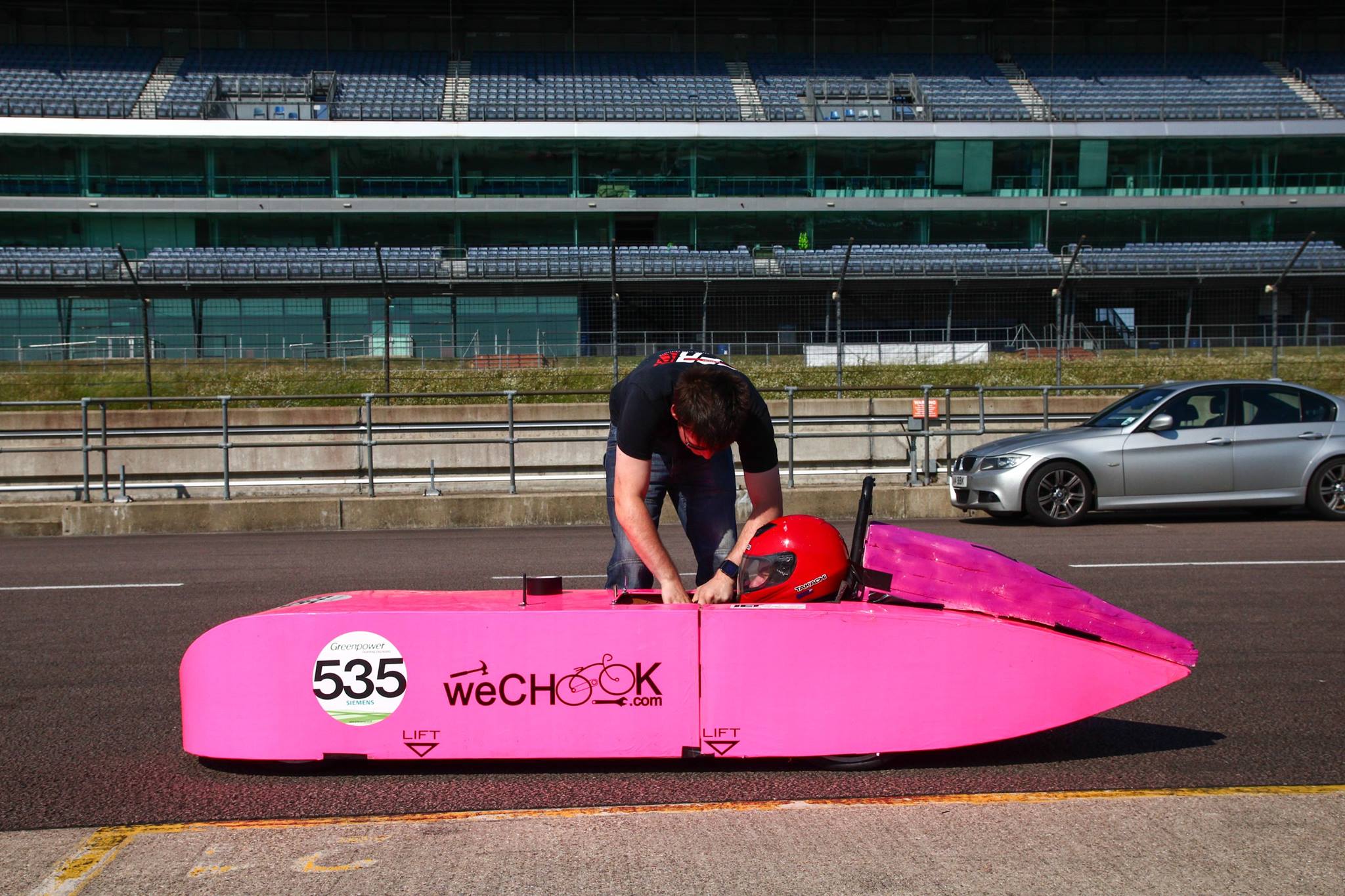
A side effect of Ian’s mad mileage one Saturday was that he had become somewhat inflexible – so much so that he couldn’t contort himself into the car with the bodywork fitted! So, once he had got in, I finished taping the car up around him and sent him onto the circuit. The car ran for 15 minutes, setting times as consistent as possible considering the volume of traffic out on track, with no catastrophic failures (although a few non-catastrophic ones!). Ian’s main complaint was the lack of left lock, which resulted in him having to brake into the first corner each lap. A quick attack with the power file allowed a couple of extra degrees of steering, although the car was still severely lacking in right lock, which remained a mystery until later in the day.

DSC00659

We noticed a few more problems – the tail had slightly debonded from the rest of the chassis, almost certainly caused by the shock loading from the ‘jump’ halfway around the circuit, and the motor had come loose in its bracket, which was a surprise considering how many times it was checked before we sent the car out. Resolving these issues was relatively quick, and we sent the car back out. The changes gave us a 5% improvement in lap time, but we ran out of test time to see how much quicker we could go. Encouragingly, we were much closer to the fastest cars than we had ever been before, even with a car that was still very much in development.

In between practice and the race, we made some more changes – new tyres were put on the front wheels, more dust was created in opening up the steering angle, and a spacer was added to the left front wheel to correct the camber. The final job was getting the car tracked correctly, before taping Ian back in and wheeling him to the line.

An immediate problem emerged, in that the car could barely turn right without the wheel rubbing on something, which hadn’t been a problem in prior testing. There wasn’t time to fix this as we were already on the way out to the grid, and fortunately we would only be going left on the track.

DSC00657

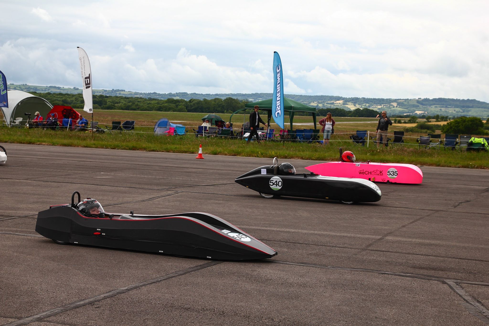
We settled in just behind EMF X1 of EMF Racing, and set very consistent times for the first 30 minutes of the race, but we were nowhere near the speeds we had achieved in practice, even with slightly less traffic on circuit. As we passed the 35 minute mark, with 26 laps completed, Ian felt a change in the car’s handling on the back corner, and immediately bought the car back into the pit lane. With the bodywork off, we immediately noted that the front wheel’s we had developed some severe toe out – one of the front headsets had come unseated, resulting in us dragging the left tyre around the straight bits of the circuit. This had taken the left tyre down to the canvas in places (if Ian hadn’t bought the car in, the tyre would have only lasted a few laps more), on a track layout that should abuse the right tyre much more.

Because of this, we decided to retire from the race – happy that the car had not had any disastrous issues (powertrain, bodywork and electrical systems were all top notch), and confident that we at least had a much more competitive baseline than we did with Electric Boogaloo – the effort was worth it after all! We did go home with a number of jobs to complete before the next race (including a few more that we discovered once back in the workshop), but nothing anywhere near as challenging as completing the car on time in the first place!

Congratulations to Dave on another victory, although we may have had a closer race had Reprobation not suffered from a number of reliability issues, and eventually retired. Great work also from the greenpower staff – scruiteneering was the smoothest I’ve ever seen it, and it wasn’t too chaotic with the density of cars and people in such a cramped pit & paddock area. We also enjoyed espousing the virtues of Electric 2galoo to the two judges from Red Bull, as well as all of the other interested parties that came and had a look – I hope we managed to give at least one person we talked to a bit of inspiration to do their own!

Next Stop… Dunsfold Park

weChook Racing: Rockingham Heat 2015

Shockingly, Rockingham did not begin with the customary camping trip. Being just over an hour’s drive away from weCHOOK Racing HQ, and a midweek event, we took the hit and left off early at 6:30, to try and miss some of the traffic on the M1. We weren’t all that successful.

We arrived to find plenty of teams already in attendance. A lot of the big players were there for the heat – Jet, 2 cars from Renishaw, 2 cars from Silesian, 2 cars from Reel Racing (from the top of Scotland), 2 cars from Driven, 2 cars (but no Dylan) from Sandbach, and Rotary Racer. It wouldn’t surprise me if Rockingham will have been the most competitive F24+ heat of the year! There were also plenty of brand new or nearly new cars there, including us, Stealth, Perkins and Bournville College.

Some of our competitors at Rockingham

Some of our competitors at Rockingham

We ended were sharing a pit box with Reel Racing (who put us to shame when we were complaining about the distance we’d have to drive to get to Croft) and Bournville College, who were attending their first race, and had plenty of questions about Electric Boogaloo! One of the best things about these events is how open to talking about their cars (almost) everyone is, and its great to be able to talk about engineering on an equal footing with many of the kids involved. I’ll always consider it to be an educational engineering event first and a racing event second, so if I can learn something or help someone else to understand something I’ll count it as win, even if the car’s last out on circuit!

The Greenpower staff looked more stressed out than ever – with the massive number of teams in attendance, we experienced our first ever ‘dual scruiteneering’ thanks to Stewart. We got through quickly and with no rectifications to be made, leaving Ian and I plenty of time to talk strategy!

Rockingham was the first event to which we’d bought our full sensor set up. After spending Tuesday evening sorting out data typing issues, we had Motor Current, Motor RPM, and a very noisy Battery Voltage signal being transmitted wirelessly to the pitlane, displayed on screen to the driver, and (probably most importantly) logged to an SD card. There’s a few more sensors to be added (wheel RPM and motor temperature are the first two that come to mind), but the core of an idea that we had at the start of 2014 is now in place: All the necessary data collection (and tools to analyse it) to do 5 laps in practice, then come in and decide exactly how to use our gearing in the race.

The new sensor setup had a second purpose. We were still lacking in a really effective motor cooling solution – we had some PC fans blowing air over the motor case, but only a few small heat sinks attached to the shaft. Merryfield had seen the motor casing hit over 100 degrees, and we were keen to avoid doing this again, as it could well have ended the race. Seeing as we couldn’t get heat out of the motor very quickly, we had to manage the amount of heat that we were putting into it. Using the readout of current in the cockpit, Ian could use the gearing to control the current, attempting to maintain an average consumption of ~24 Amps, and not allowing peaks of over 30 Amps.

In the pits between practice sessions

In the pits between practice sessions

The visible effect of this strategy was seeing the car blasting down the hill at near the speed of the top competitors, and then slowing right down on the way back up again. I’m tempted to break into pontification about ‘Constant Speed’ vs ‘Constant Current’ control, but I think I shall dedicate an entire post to that at a later date.

Having invested in a third pair of batteries after Merryfield, we had a bit of leeway for our testing in practice. We ended up running two stints, totally 16 laps. The first was to allow Ian to get used to using the gearing with the current sensors, and to get baseline on our power consumption. The car was behaving well, setting the highest speed lap that the car had achieved up until that point. Using the data collected in the first stint, we selected some areas of the circuit to deploy more power, and areas to conserve power. In this way, in the second stint we managed to increase speed by another 2 mph, without increasing total power consumption.

Having nailed down our strategy in practice, we did some final setup and waited for our race. We used to break to poke around some of the competitor’s cars, in particular investigating the maximum steering angle of Reprobation and Silesian’s Bullet cars. It became apparent from this just where we were losing out – both of them had a tiny frontal area compared to Electric Boogaloo. We also had an entertaining interview with Gav!

We lined up about halfway down the grid for the race, and got away relatively quickly. By the end of the first lap, we’d dropped down the field by a few positions, but we were keeping power consumption under control. As the race wore on, we began climbing back up the field, aided by both Stealth and Silesian’s Bullet II running out of power. in closing stages. We ended up just outside the points, but with the quality and quantity of the competition, this was a more impressive result than the 7th place finish at Merryfield.

Just beating Stealth to the line!

Just beating Stealth to the line!

We left the event with good confidence in the potential of the powertrain, but knowing that we’d never be truly competitive with car in its current form, due to its size. So, Rockingham turned out to Electric Boogaloo’s final race, and I should probably get back to finishing off the new car!

Electric Boogaloo, after Rockingham

Electric Boogaloo, after Rockingham


weChook Racing: Merryfield Heat 2015

As it often does, our race day started the evening before, by packing the wagon and heading down to a local campsite. As a slick and streamlined operation, we had the car packed in about 15 minutes, and started our cruise down the M5 in good time.

We were quickly joined at the campsite by our regular camping buddies – Driven – and enjoyed a few quick drinks before hitting the rollmats. Morning came around and we packed up, set off, and got to the track all in good time (a first!). Registration and scruiteneering were dealt with quickly (although not without Josh taking a worrying number of photos of our car), leaving us with time to spare before practice began.

DSC_0118

A glorious evening for camping

We took the opportunity to poke around the cars of some of our competitors. We were particularly interested in a new privateer entry called Stealth, which made interesting structural use of foam, and ‘borrowing’ ideas from Renishaw on how to make lightweight, streamlined bodywork. By this point we had realised that our bodywork was simply too large, and had begun planning our the rework to occur in the mid season break. Reworking eventually became starting again from scratch, but that’s a subject for another blog.

DSC_0126

Calibrated spy shots of the competition

Performance in practice didn’t look too bad, with us sitting just behind Project E, but ahead of Rotary Racer, one of Renishaw’s cars, and Stealth. The lap times were unfortunately only half the story though; the front tyres had been shredded, and we were drawing an average of nearly 40 amps, meaning we’d never finish the race.

The tyre shredding was being caused by the car’s tracking being slightly off. Fixing this (with some help and kit from Driven) dropped the average current consumption by 15 Amps, but still left us consuming far too much to make the end of the race.

11430120_10207307023620177_755738890211142662_o

F-eV, Stealth and Electric Boogaloo on the start line

With the risk of not finishing, and completely cooking the motor over an hour of running, we decided to take a conservative approach, lifting and coasting around the corners, and running much higher gear ratios than we had in practice. These changes cost us around 3mph over the race, but made sure that we saw the chequered flag. We dropped back at the start of the race, but by the end of the hour had made our way to a points paying position, thanks to the failures of other cars.

At the event we took the opportunity to buy two new batteries, taking us to a total of 6 (a necessity with the new format of the International Final), and a new motor, as we were reasonably sure at this point that we had irreparably damaged our original (more on that in another post as well).

We left Merryfield with our first race finish (Hooray!) and our first points of the season (Double Hooray!), but also a much greater awareness of how much would need to be done to get to where we want to be.

Next Stop: Rockingham!

11406241_10207307058701054_1130153361834020471_o

Donkey Kong driving position is poor for aero…


weChook Racing: Goodwood Test 2015

As ever when we travel to Goodwood, the event started on Saturday afternoon. Driven kindly offered to take Electric Boogaloo in their van, as our intended transport vehicle was suffering from being an Alfa Romeo, and could not be trusted to get there in one piece.

Goodwood Van

Once the van was seen off, we piled into the ST with our tents and set off down the M40. A couple of hours later we arrived at our usual campsite (which is just shutting down, what will we do?!) and pitched, before heading off to the pub for dinner and some triple cooked chips.

For the first time in 5 or 6 trips to Goodwood we managed to get up and set off at the time we planned to. Unfortunately I then got a bit lost, and wasted all that time we’d gained! Once we eventually got to the circuit and set up our paddock, we went straight for the scruiteneering queue before it got too gargantuan, and settled into the routine of telling people ‘No, the car isn’t actually finished yet, we’re going to do some bodywork soon!’.

Scruiteneering was a bit of a challenge; I don’t think any of the guys were used to seeing a car with so much still exposed! Fortunately, the two of us know the rulebook inside out, and after a few discussions, we were given our MOT sticker, with only a couple of things to sort out before the next event.

IMG_9316 (3)

With that, we were ready to get out on circuit! Ian wedged himself back in, and we trundled over to the pit lane. After a final quick check of the electrical system, Electric Boogaloo was ready to go!

At this stage we really had no idea how well the car would go. It had had a few runs up and down the road, never really getting past 20 mph, and not doing any representative cornering. Would the steering be any good? Would the chain come off? Would the whole thing just fall apart once it got up to speed? We just didn’t know!

After a nervous 5 minutes, the car came blazing through the final corner, and past us down the main straight, with barely a sound considering the exposed powertrain. The second lap time around it looked even quicker, putting in what was at the time the third fastest lap.

Ian came back in at the end of the third lap, and a few issues were immediately apparent. Firstly, the motor was rather warm. Secondly, there was a puncture. We rushed back to the pits to sort these issues out, with an inner tube ‘borrowed’ from Driven, and a saw to increase the motor cooling. We just about got it all sorted to get the car back out before the end of the session, but were bought back in again before we could complete a whole lap.

With a few laps under our belt, and no breakdowns or chain-offs, we were feeling pretty satisfied! Better still, some of the smirks from the start of the day had turned into begrudging compliments, having seen how well the car was going.

The afternoon saw more of the same. We set our fastest lap at 30.3 miles per hour, but suffered from quite high current consumption and motor temperatures – somewhat inevitable running a car with all the aerodynamic qualities of a brick! Ian still managed to do plenty of overtaking though!

We managed pretty much a race distance over a couple of stints on track, with no mechanical failures (almost unheard of during my time with Driven!), and we learnt plenty about how much steering lock we need, and how the gearing/motor controller can be used to our advantage. We developed a pretty extensive to do list in order to have the car really ready for Rockingham, which is now just a few short weeks away.

Away from the track, it was fantastic to catch up with all the other Greenpowerites that we haven’t seen since the National Final, and chat about cars with people as enthusiastic as we are! I was particularly impressed with the work done to Probation IV, it could barely be recognised as the same car from last season. As ever, Dave looked imperious in Jet, and we were keeping a close eye on the aero-mods he was trialling to see if there were any ideas worth… appropriating.

Thanks to Greenpower for organising another slick event, and I’m looking forward to the next one! Hopefully we’ll see you all there!

weChook Racing – Greenpower Motor Testing part 2

Introduction

After testing two brand new Greenpower motors (https://wechook.com/?p=321) we borrowed the two motors that had been fitted to Project E and C-XeVolution for the last season.

We were aiming to determine how effective these motors were compared to the new pair and to each other.


Background

Over the course of the season, the two motors fitted to C-XeVolution and Project E had both covered hundreds of miles, so we wanted to determine whether there had been a significant gain or loss of performance from the extensive run in. Unlike C-XeV’s motor, nether of this season’s motor’s has been significantly overheated, however the motor from C-XeVolution did get warm at Castle Combe and the International Final, due to the hills.


Test Procedure and Equipment

The used motors were tested using the same equipment as the new motors. This time, we decided not to attempt the highest current draw using the heated seat pads, as the results were not reliable enough. In order to test at the higher currents, its likely that we’ll have to add more bulbs.


Results

Shown below are two plots. The first shows a comparison of the 4 motor’s efficiency plotted against motor rpm, the second shows efficiency plotted against battery current.

Plot 1

RPMpart2

Plot 2

Currentpart2

Conclusions

When plotting the motor’s efficiency against current, C-XeVolution’s motor is comparable to the second new motor, however it must run much more quickly in order to achieve this efficiency. Evolution’s motor’s performance appears to be tending towards that shown by C-XeV’s motor in the last test report, suggesting that the extra heat it experienced at Castle Combe and Goodwood may have started to cause some damage.

Project E’s motor also appears to need to run at a higher speed in order to achieve its peak efficiency, although it is more efficient than the first new motor over most of the tested speed range.

It suggests that, if we had managed to the run the motor at ~2000 RPM, rather than ~1700RPM, we would have been in a much more efficient range.


Further Work

Further testing of the new motors after a more extensive run in will allow us to see how efficiency is affected by distance and thermal cycling. The motors will be cycled using a power supply to start with, and then run in anger once the rest of Ramjet is complete.

We also need to develop a more reliable method of testing the motor at higher duty, in order to better compare motors at the speeds they tend to experience during a race.

weChook Racing – Greenpower Motor Testing part 1

Introduction

As part of the development process for Ramjet, we have been testing a pair of brand new motors, as well as an old (and heavily abused) motor that was used in C-XeV –  Driven’s 2012 competitor.

The aim of the testing was to calculate the comparative efficiency of the two motors, and develop an insight into how the motors perform at different speeds and powers (and see what a really bad motor looks like as well!).

Background Information

During a Greenpower F24+ race, the motor is run using two 12V Lead Acid batteries wired in series to generate the required 24V. Bench testing has shown that an average current draw of ~22Amps or less is required to reach the end of a race without over discharging the batteries, or ‘falling off the cliff’. If the battery is discharged to the extent that the voltage begins to collapse, lap times at the end of a race can be severely compromised. This can be seen in C-XeVolution’s performance in the Greater London F24+ Heat, when compared to Project E. (504 compared to 711: http://bbk-online.net/gpt/lap213.htm)

Over the course of the race, Project E lost 6 seconds compared to its fastest lap, whilst C-XeVolution dropped nearly 40 seconds. In the race, C-XeVolution was consistently consuming an average of 24 Amps, whilst Project E was consuming 21 Amps.

On a race by race basis, current consumption is controlled by gear ratio. In order to most effectively select a gear ratio, a good understanding of the motor must be gained. Adding further complexity to the mix is the fact that the profile of each circuit varies so wildly. At Dunsfold Park, Project E’s current consumption stayed consistently between 18 Amps and 23 Amps, whilst at the National Final in gusty conditions, the current dropped as low as 15 amps on the main straight, and topped 35 Amps uphill. As such, simply investigating the motor performance at the intended average current would not be enough.

Test Procedure and Equipment

The electrical lab-car, built at the start of the year to develop and test Driven’s 2014 electrical system, was used to test the motors. The test motors were attached to another, spare motor, which acted as a generator powering a number of bulbs. The number of bulbs in the circuit, and thus the torque applied to the test motor, was controlled using a separate arduino board.

Using a current clamp and a voltmeter, we recorded the power into the drive motor, and out of the generator across a range of different output currents. We also used a tachometer to measure the motor’s shaft speed. It’s been assumed that at a given rpm, the generator’s efficiency will be same, independent of the motor being used to drive it. Thus by comparing the two new motors on a plot of efficiency against rpm, we can eliminate the efficiency of the generator from the equation.

Following the first test session, the motors were run in, unloaded and from a power supply, for 3 hours and 12V and 3 hours at 24V. Once the motors had been allowed to cool down after this, they were tested again. We decided to add some more load to the test rig for the second set of tests, to understand the efficiency at lower rpms/higher currents. These loads were not as stable in their power consumption as the bulbs however, and so there is less confidence in the results at a higher current.

Results

Below are three plots. The first shows the motor/generator system efficiency against motor RPM, and the second shows efficiency plotted against current output from the generator, which is broadly analogous to load on the motor when racing. The final plot is a repeat of the first, but with C-XeV’s motor included.

Plot 1

RPMnoCXeV

Plot 2

CurrentnoCXeV

Plot 3

RPMwithCXeV

Conclusions

Compared to the two new motors, C-XeV’s old motor ran at a significantly higher speed when unloaded. To achieve the same current output from the generator, it would require more current from the power supply than the new motors. Due to the higher speed of the generator, its voltage output was higher, masking somewhat the motor’s inefficiency. It is inarguable however, that it is less efficient at the speeds experienced during a Greenpower event that the two new motors.

When comparing the two new motors, there is a noticeable difference, with Motor 1 having an efficiency 5% or more greater than Motor 2. The margin increases towards the top end of the powers seen during a Greenpower F24+ event.

After the run in period, both motors showed a lower peak efficiency. The gap between the two motors at lower speeds decreased, and the peak efficiency for both motors appeared to be at a higher current. The second set of tests also showed the folly of allowing current to reach 30 amps or above. Efficiency quickly dropped off and the motor began to noticeably heat up.

Based on this testing, it appears that the motor’s peak efficiency lies between 13 and 16 Amps. It is also known, based on Peukert’s Law that a batteries effective capacity decreases the more quickly it is discharged (Have a look at wikipedia: http://en.wikipedia.org/wiki/Peukert’s_law, or Chipping Sodbury’s page: Greenpower Science).

To me, this suggests there may be an alternative race strategy, that involves running less aggressively, at peak motor efficiency and a low battery discharge rate, for a portion of the race, before moving to a low efficiency, high power mode for a blast to the line. Whether this strategy is quicker over the duration of a race would depend on the battery’s Peukert Constant, the change in motor efficiency at different currents, and the overall aerodynamic efficiency of the car.

Further Work

Further work will involve further running in of the motors, before another testing session, and performing the same series of tests on the motors fitted to Project E and C-XeVolution (Driven’s last two cars) for the 2014 season for comparison. Both motors have been well run in, and neither has been significantly overheated, which will make for an interesting comparison both to the brand new motors, and the very much overheated motor from C-XeV.

A new work stream opened up by this testing is to investigate the possible effectiveness of a split strategy, running slightly slower at a super high efficiency, to allow a final blast towards the end of a race. In order to determine the worth of this strategy, a better understanding of the battery and motor performance will be needed.


Mazda 3 – Shoddy Seat Fixing

Whilst fixing some bike wheels for the Driven project Rowan, a member of the team, mentioned that he had recently been having some problems with his nearly new (well at least in terms of my car history!) Mazda 3. Specifically he had a drivers seat mounting that had failed causing the whole seat to rock around with over and inch of play.

We decided that this should be a nice quick fix and a good excuse to whip out the welding gear. I have written this up purely becuase the terrible quality of these seats makes me feel that oithers will find theirs fail and may want a quick guide on what to do when this happens!

2014-08-30 16.45.462014-08-30 16.59.48

The seat came out quickly with 4 bolts in the corners, the most time consuming part was actually trying to disconnect the airbag/heated seat connector found underneath the squab (not so hard once you work out how the connector works, just play around a little).

2014-08-30 17.03.522014-08-30 17.03.37

Once we had the seat out we could assess the damage. Rowan had told me already that he had already had to use a jubilee clip to hold the rails on to the pins, this appears to be where the sprung washers have failed and gotten lost. They don’t seem to be easy to find in the correct sizes and a jubilee clip appears to function well enough for now. (Example photos are above of a ‘good’ rod connection to the rail and a slightly more custom one)

2014-08-30 17.03.302014-08-30 17.06.042014-08-30 17.14.12

The pictures above show where the bracket has failed. It’s difficult to see from but this section connects the main seat base the rails. It is hard to believe this has failed. It is eaily 4mm thick steel and it hasn’t failed around a weld or joint. With a bucket of water on hand and using some leathers to protect the seat cushion I used my Black & Decker Powerfile to clean the metal (excellent tool) and then used the mig to set it back in place. Once the part had cooled we put the seat back together and back in to the car. In true haynes style this process was reverse of removal and just like that the seat was solid again.

Driven Electric Race Car – Heated Battery Boxes

For those of you who have been paying attention I have been working on a project called ‘Driven’ for the last 18months. ‘Driven’ is a single seat electric car project where myself and other Jaguar Land Rover graduates design and build a car to race in the Greenpower race series. On this project I had some help from Zoe and Will, graduates in the year below me on the scheme who will be taking over the project when I leave, thanks for the help guys!

The lead acid batteries we use in our electric car are heavy and the team needs an easy way of transporting them to races and storing in the workshop. Currently we use insulated battery boxes to store our batteries in, transport them to the race however, the boxes are too large and have no way of actively heating their contents. Since batteries are allowed in the rules to be heated to 25degC it makes sense for the team to always be running the batteries at this temperature: with lead acid the warmer the battery the more capacity we can get from it (within reason).

Solution: New battery boxes that incorporate a 12V heated seat pads from old car seats. These will allow us to both transport the batteries and warm them prior to a race simply by plugging in a spare car battery. By making the box just big enough there isn’t too much excess air in box that has to be heated up.

For this project I actually constructed a list of requirements before starting the build:

  • 2 boxes should be constructed to hold 4 batteries each (4 batteries are used per car for race days and the team has 2 cars).
  • Boxes should be easily moveable
  • Boxes should be easy to strap in to the van for transport
  • Boxes should use a Red SB50 anderson (12V) for power connection to the heated pad, this is the teams standard connector
  • Boxes should be made from a wooden frame base with plywood cladding
  • Boxes should look presentable, logos on side prefered.
  • Lids should be removable and allow charging of batteries inside the box + battery access.

IMG_20140619_193352IMG_20140619_192841IMG_20140619_193727IMG_20140619_201508

The bottom frame of the box is made from 2×4. This effectively transmits the weight of the batteries to the castors and gives space to insert a piece of insulation foam. A heated seat pad is re-purposed and simply pressed in to place using the piece of foam. Holes are drilled in the bottom of the plywood base for temperature sensors and to give an easy way to push the foam and pad out in case of maintenance. Castors are mounted so that the box can easily be pushed around the teams workshop.

IMG_20140620_183851IMG_20140620_185634IMG_20140620_185644IMG_20140620_190859

With 2 bases completed Zoe cut up the plywood sides while Will and I glued and screwed them to the base. Extra timber is used inside the box to stiffen up the corners and give the insulation something to press up against. The 50mm insulation is easy to cut with a saw and simply presses in to place, it seems to hold any heat in very effectively.

IMG_20140621_102837IMG_20140621_103740IMG_20140621_105122

A quick coat of paint and some securing handles later and we are finished. Another nice quick project that should help the team for many years to come. Now we just need some nice ‘Driven’ branded stickers to add the final touch.

IMG_20140621_162947IMG_20140621_164500IMG_20140621_165226IMG_20140621_173701

Leamington Raft Race – 2014 – Vanessa’s Return

It’s that time of the year again, the annual Leamington raft race, organised by the Rotary Club of RLS. My team and I had so much fun last year that we decided to go for it again, after making a few upgrades to last years set up.

Van-essa, the van roof come boat has been sitting in my garden since last year but all she really needed was a good clean and a little fibreglass to repair some of the larger holes we picked up at the last race. We prefer to think of Van-essa as a boat that sinks constantly…but predictably. The main issue we were having last year was that the boat did not want to go in a straight line. Primarily I think this was due to the ribs running horizontally along the roof, acting like chinings but in the wrong direction. The boat isn’t much longer than it is wide so this seemed to give it a tendency to veer off course at every given opportunity. To fix this I attached 2 pieces of hardboard (not ideal but cheap) to the bottom of the hull to flatten off the underside, then added some 2×4’s to both stiffen the hull slightly and force the water to flow in the correct direction. This was all screwed up through the hull and in to the inner frame, small screw holes would leak slightly but it was a nice quick way to attached the sheet besides, going quicker would mean less time in the water which would mean less water would make it in to the boat?

IMG_20140601_132833IMG_20140601_132824IMG_20140614_160947

This solution clearly worked pretty well, 17mins shaved off of our time for last year an a very respectable 3rd place. The boat seemed a lot easier to steer but perhaps that was just me being optimistic, the sped up footage below makes us look like we are playing a game of Pong to get along the river!

The smaller amount of work on the boat meant that I could focus more time on the trailer! Last years design worked fine but was pretty dangerous and a lot of hard work. I wanted to address both of these issues and fortunately a quick call to Action 21 in Leamington soon saw me with a few steel bike frames to play with.

IMG_20140505_114430IMG_20140613_134653IMG_20140613_134649IMG_20140610_202429

I am calling this a ‘bicycle pick-up truck’. It has full suspension and 2 front V brakes (plenty of stopping power for the speeds we were achieving). Both bikes are welded together and extended (3 and a bit lengths of chain required per side!), with the steering linked with some rudimentary Ackerman set up. A bed made from 2×4’s and OSB was bolted to the back to give me something to rest the raft on. Not only does this solution allow for 2x the power of my previous design, it is also much more stable and comfortable. We certainly got a lot of great looks cycling it down the parade to the race. Both bikes are set up with a single gear ratio and despite having a lot of chain droop we didn’t drop a chain once!

FB_IMG_1402666157028

This year we managed to get some video of the race/eventful journey to it! So here is is in full, my first proper attempt at video editing, thanks to Matt for getting the shots on the way down. If you were a big fan of Van-essa the boat I suggest not watching the final 30 seconds, where she meets her end, sorry all I just can’t keep it in the back garden for another year!

Thanks again to the great team who crewed with me and helped prepare the boat for race, we will be back next year with a much faster design to hopefully take home gold.

Globetrotter Tandem Restoration Project – Bottom Bracket Fun and Finishing Up

It has been some time now since I purchased my 1973 French Tandem. This great find on ebay was supposed to be a quick restoration project however, the project quickly got out of hand when I realised the bikes origin. Old French parts are now hard to come by and pretty much the entire bike required some form of TLC. So began a full rebuild/conversion to more modern components.

FB_IMG_13971520037810500FB_IMG_13971526030268371
First problem I found was the wheels. Though I loved the idea of using the original wheels complete with hub brakes (often used on tandem bicycles during long descents to avoid heating the rims and exploding tyres!) these were old steel walled jobbies, no way near as good a braking surface as more modern rims. The hubs also needed a serious service and some spokes needed replacing. On top of all of this they were an odd size wheel which makes buying modern tyres more difficult. £45 picked me up a used but good Rigida Sputnik 700C wheelset, nice strong rims with shimano disc hubs, these fit the frame despite the slight change in diameter.

The new wheels meant I had to change the front fork. This was also convenient as the headset from the original bike was beyond repair, and finding one that would accept the old fork steering tube seemed impossible. A 700C steel fork was found with cantilever brake mounts that would fit a modern threadless headset. Conveniently a modern 1-1/8th threadless headset fits perfectly into this frame, finally a part of this build that seems to be on my side! I found a set of cantilever brakes taken from my touring bike and fitted these as the primary stopping power. A quick bit of welding on the rear of the frame has resulted in a disc brake mount for the rear wheel, I will use this at some point if I find that the rim brakes aren’t giving enough stopping power for 2 riders descending.

IMG_20140401_175405IMG_20140401_175209IMG_20140401_193105IMG_20140401_194034

The main issue I had with the frame was the bottom brackets. Both of the existing units were totally unusable and finding new units to fit the existing frame threads was proving difficult. Some research uncovered some options such as re-tapping and using an Italian threaded design. Other options were to use special brackets that don’t utilise the threads in the frame at all and instead just fasten in 2 parts to each other (like a nut and bolt but with a bottom bracket inside). All of these options were prohibitively expensive, especially when you consider that the rear bottom bracket on a tandem is known to take a bit of a beating and requires more regular replacement.

To get around my bottom bracket issue I decided to cut the old shell out and weld in a new shell that would accept a threaded English bottom bracket. Perhaps not the neatest solution but certainly cheap at just over £6 for each pre threaded steel shell. The front bottom bracket was fairly easy to accommodate, due to it being an elliptical type set up that is pinch bolted by the frame. This allows the sync chain to be tensioned by rotating the elliptic bottom bracket and bolting the gap closed. Some 5mm sheet steel was cut and welded in place to fashion my own version of what the frame came with, only this time with a nice modern thread.

IMG_20140406_131139IMG_20140406_131132IMG_20140406_140258

The rear bottom bracket was slightly more of an issue. Care was taken in cutting out the existing shell and then perfectly lining up the new shell in place. This is a highly stressed area on the frame and I wanted to make a neat job of the welding. Some chooking later and the frame is back in one piece, only this time with a modern thread.

IMG_20140503_191816

The frame and new fork were then sprayed with some Rustoleum using my HVLP spray gun in a rudimentary booth outside, the finish isn’t fantastic but it is certainly a tough coating, ideal for this build. I built the bike up using new cables and some spare parts I had from various other builds. I am pleased with the end result but I am still not used to riding on the back, the lack of control you feel as a stoker is something I will have to learn to love.

We then tried to ride the tandem solo, from the back. here is a video of my house mate Ben attempting the fairly uncomfortable ride.

Gear Indicator – MGZR Rally Car – Version 2

Wow it’s been a long time since I posted here apologies, I’ve just been doing a lot of engineering…..which I will now attempt to write up from scraps of paper and numerous logbooks.

After a successful set up running for a few journeys, counting gears and displaying them correctly, Adam has been having some issues with the gear indicator that I made for him. A quick diagnosis showed that some of the power supply debouncing caps had been rattled loose (rally cars are a harsh environment to engineer for!) which was causing some spurious switch presses to be seen by the msp430. This problem quickly manifested itself by counting gears erroneously.

While we were fixing the issue I decided it would be best to ‘re-invent’ the gear indicator system now that we understood Adams requirements a little better. Firstly we decided to go for a much larger 7 segment display, choosing a 25.4mm model that required a 5V forward voltage (2 series LEDs per segment). This is both bigger and brighter which will help Adam see the display in future events. This added some complication as the msp430 on the board runs a 3V3. To get around this I dug around my electronics collection and found a uln2004a (transistor array from TI), this allowed me to switch the 7 segment easily using the msp430 GPIO. As can be seen in the pictures 2 LDOs are now required but the main design hasn’t changed significantly.

IMG_20140727_160358IMG_20140727_160403

The extra ICs (plus the fact we wanted a more robust solution!) has meant that for V2 I have switched to using breadboard. I should have done this in the first place really but hadn’t appreciated how much space I had to play with behind the dash. Note to self: fully understand requirements before inventing a solution. Hopefully this will mean the indicator will be less susceptible to vibration.

I also found some bugs in the code where I was setting up ports for the LED. These have now been fixed and the latest code has been uploaded below. Hopefully this final design will suit Adam’s needs, I will keep you up to date with his progress.

GearIndicator_source_V2

STM32 Programming

Merry Christmas all. Over the Christmas break I have found some time to put together some of the telemtry and control system I have been designing for the driven electric car. I have written this post primarily for my own benefit as it has taken me a couple of hours to get to a stage of programming my board which would have been avoided had it not been for a simple misunderstanding.

The main ‘brain’ of the board is an STM32F103RB, fantastic bits of kit and my first push away from the AVR family I had become so comfortable with at university. At the time of writing I have designed and soldered up a test PCB and have been plating around with getting a program on to the STM.

I am using my STM32VLDiscovery board’s built in STLink-V1 as a SWD programmer. A simple procedure to wire up between the boards (discovery and my pcb) and get comm’s…AS LONG AS YOU DON’T NEGLECT THE ANALOGUE VDD PIN. I had not forseen the importance of connecting this pin initially and had left it disconnected (for the simple reason I couldn’t find the 0603 inductors I had ordered to nicely smooth the analogue supply line going IN to this pin. After a few hours headscratching, checking and rechecking for shorts, I finally found this disconnected pin to be the source of all my problems. Christmas truely has come early.

So watch out for this in the future Ian, and hopefully this note may help someone else in the future.

Gear Indicator – MGZR Rally Car (part 2 – Installation)

During one of our many days off work (must be taken before the end of the year) Adam and I finally got around to installing the Gear Indicator in his rally car. Since Adam put in the request for this project back in March he has crashed and subsequently repaired the entire front end of the car. Not great news for him but every cloud has a silver lining, and the great news for me is that Adam has put some weChook graphics on the newly painted wings.

IMG_20131127_102524.jpgIMG_20131127_102519.jpgIMG_20131127_102511.jpg

The final step in getting the indicator working in the vehicle was designing a bracket to hold the microswitches in position around the gear lever. Some experimentation and we settled on a design made from a single aluminium plate that utilised the bolt holes already holding the selector bracket.

Once the microscwithes were mounted on the plate and the wiring tidyied we powered the indicator on (from a spare 12V fused feed) and went for a test drive. The indicator worked perfectly when the engine wasn’t running however, alternator noise on the power lines sometimes led to miscounted gear shifts when we drove the car. Note to self: cars are an incredibly noisey environment so make sure to add smoothing capacitors before you pot any projects. Fortunately with this modification the device seems to work perfectly and Adam hopes to test it out on a rally in the near future.

I have included a couple of videos of us testing the indicator:

Gear Indicator – MGZR Rally Car

It’s been a while since I have posted on the blog. The Driven Telemetry and Control project I am working on is taking up a lot of my time (now I have taken the role as Electrical team lead) and as such I have spent almost no time on the eCumbent or the Tandem.

Fortunately I found some time this evening to finally complete this little project so thought I best update weChook before my time is further absorbed. A friend of mine, Adam, has recently purchased a rally prep’d MG ZR complete with a sequential gearbox. Though the box seems fantastic and allows him to shift quickly through the gears he currently has no way of knowing which gear he is in, since the lever is a simple push pull type.522090_10151383225391914_1086446565_nThis quick project will hopefully help him with the confusion. A simple up down counter implemented using an MSP430G2211 increments and decrements through the use of 2 micro switches. These will be fixed at the base of the gear lever. The output is handled by a 7 segment LED display (blue, of course) which shows the current gear (Gears: n, 1, 2, 3, 4, 5, 6). Since joining Jaguar Land Rover and discovering the beauty of ‘surprise and delight’ features I have incorporated a gimmick in to this project: it spells out the drivers name at initialization.Gear IndicatorI haven’t bothered building a PCB for this design as it has so few components. The MSP430 is just soldered to the back of the LED and other components glued around. Adam plans to pot the indicator when we are fully happy with it’s operation anyway.

I have made the following available for this project: Source, Schematic

Globetrotter Tandem Restoration Project

Like all good engineers I like to have too many projects on at any one time. In the true spirit of this I have picked myself up another one! After this years L2B bike ride a friend and I decided we HAD to do the event next year on a tandem bicycle. The idea has lay dormant for a few weeks until I saw a stunning tandem bicycle come up on ebay for a reasonable price and close to my house. A quick bid later and I am now the proud owner of a Globetrotter Tandem bicycle.

Globetrotter tandem

The bike is in need of some work but hey, I wouldn’t enjoy riding it as much unless I had built some bits of it myself. So the project begins.

I have started by completely stripping the bike down. It will be sandblasted then I can give it a quick lick of paint. In doing this I have noticed that I am going to start having some problems dragging this tandem in to the 21st century. Both bottom brackets are in poor condition as is the headset. The worry now is that everything on the bike seems to be strange old French standards, unlike the classic 1″ threaded headsets and cartridge bottom brackets I have become used to.

So this is as far as I have got so far and I am already sensing the project will spiral out of control (instead of being a simple resto). Nevermind! I will keep you updated as things come together.

Aerodynamic bicycle wheel coverings

It has been some time since I have stayed up til 1am working away to get a project done. It seems once you leave University and start working for a big company times like this are rare and I find myself missing the feeling of satisfaction when, at the end of a long session of chooking, you get to go to sleep.

Fortunately this void has recently been filled by Driven…..from my projects page, ‘since starting my graduate scheme for Jaguar Land Rover I have joined the ‘Driven’ engineering project. A team of graduates who design and build a new car every year for an electric vehicle race hosted by Greenpower.’

So far the Driven project has helped me meet many talented people all with the common goal of making an electric vehicle. This has also presented some unique challenges as the team is far bigger than those I have worked with in the past, with the idea behind this being that we function as a microcosm of the overarching company. In addition to building a car every year the team hopes to (and hopefully succeeds in) inspiring the younger engineers at the race events. I plan to use this blog to document some more of my work for the car in the hope that some principles can be applied by other teams to their cars.

Covering the wheels of our cars we can reduce the loses we have due to aerodynamic drag and hopefully this will increase our top speed and efficiency. Although I am no aerodynamics expert I am aware that a spinning wheel made of spokes presents a drag factor when those spokes are moving through the air. My housemate Shawn would be able to describe the effects of this in far more detail than I can but essentially forcing more air to move in and around the car is BAD.

As well as the spokes going through the air creating turbulence we also want to make the side of our car as flat as possible so that the air is passed down the side, rejoining neatly at the back. Since both our Driven cars have open front wheels covering these can further improve (reduce) the drag coefficient of the body. As an added bonus covered wheels can look pretty cool.

This is a quick and easy way to cover wheels we have been experimenting with. It is cheap and can be done easily at home (this was done in my kitchen). So far I haven’t done any quantitative testing on these wheels vs uncovered but as far as I know the aero benefit should outweigh the slight weight penalty.

Tools used:

  • Stanley Knife
  • Hole Saw + Drill
  • String
  • Pencil
  • Electrical Tape
  • Cutting board
  • 1 screw / nail
  • 1x beautiful assistant, thanks Ben!

We started our build with a big sheet of thermoform plastic, around 1 – 2mm thick should be perfect. Ours is thermoform but only because it is what we could get our hands on, any plastic should work here. We did try some basic thermoforming but found that the plastic would just sag on to the spokes and create a very wavy surface.

IMG_20130627_221956IMG_20130627_231921IMG_20130627_231949IMG_20130627_232038

Start by drilling a hole where the centre of the wheel will go. We then insert a screw in to this to act as a centre reference. A piece of string and a pencil can then be used as a giant compass to draw a circle of approximately right size to suit your wheel. Cut big to start with, it’s always easier to make the circle smaller than bigger if you go wrong! Once you have your circle drawn you should be able to use a stanley knife to cut around the line. Be careful here.

I apologise for the poor picture quality, it was late and my kitchen isn’t the most photogenic place anyway (though much improved by a photogenic assistant!).

IMG_20130627_232547IMG_20130627_232630IMG_20130627_233422IMG_20130627_234346

Next up select a hole saw that is a bit bigger than a convenient flange on your hub. Use the hole we drilled earlier as a guide and the hole saw create a bigger hole.

Now the ‘overlap’. Our wheels (like all bike wheels) are slightly convex in that the hub sits out wider than the rim. This means that a flat piece of plastic won’t simply fit on top. To overcome this we must create a very slight cone to fit the wheel. This ‘overlap’ method is far from perfect as it does create a slight bump on the wheel which makes for a not perfectly flat surface, however, it is easy to achieve at home.

Start by cutting from the inside of the cover to the outside. Then place on your wheel. It should be noted that as the outside of the cover is pulled down to the rim a natural overlap can occur at the new cutline, simple. At this point you may have found that you have to adjust the size of your cover. Ideally you want to have around half of the rim showing and half of it covered as this will make life easier in the next step.

IMG_20130627_234125IMG_20130627_234355IMG_20130627_234630IMG_20130628_002035

Next we run a line of electrical tape all the way around the outer edge of the rim. Covering the new cover and then folding some over the edge of the rim and in to where the tyre sits. Electrical tape actually seems pretty good at going around the circumference of the circle and with practice I can always do it in one long pass. A piece of tape neatly covers that overlap line and then we finish the wheels with some black hot glue just to hold the centre to the hub. It can be worth doing both sides of your wheels, just remember you still have to have access to the valve holes! I just cut a small window on the inside covering to allow access to this.

Leamington Raft Race

Recently some friends and I decided to enter the Leamington Spa Rotary Club Raft Race. With a few weeks to go we were still struggling to source some kind of buoyancy we could easily get a hold of for free. Eventually this led to the realisation that the roof from a van would make a perfect boat, all we needed was a roof. A quick call later and we had secured one (nice work Robin and the guys at Truck Busters), and that Friday we went equipped with angle grinders and a large trailer.

After scouring the lot we settled on a lovely white LDV convoy. This had the advantage of the side door not interfering with the roof (one less hole to fill), a high roof line and, most importantly, it was fibreglass so wouldn’t be too heavy for us to move around. An hour or so later and we were done.

960205_10151480037894473_2016859474_n405572_10151480037424473_491933501_n101_0005101_0008

Some cutting and re-welding was done to remove as must rust/weight as possible. Shawn and I then cut a piece of 6mm ply to make a stern (where the rear doors went). This was sealed on with silicon sealant and screwed in to the metal frame around the back. Although this mostly held water out during testing we later added some ‘sticks like shi*t’ to fully seal the joint.

101_0032101_0040101_0068

A floor was added to spread the load of the 9 occupants of the raft across the fibreglass, then decoration was all that we required to be ready for the race. This lead to the problem of how to move a 4m long and 1.8m wide ‘boat’ 2 miles down to the river. None of us owned a big enough car trailer and it was too big to go on to my roof rack.

Enter the Bike Trailer

In the UK there are plenty or laws about towing by car. However, I could find fairly little relating specifically to towing by bike (note: this does not guarantee this is legal). A giant trailer could double up as a launch for our boat and be towed, albiet slowly, behind my mountain bike. Fortunately I had some spare steel left over from our Ambulance Adventure so I managed to whip together a bike trailer fairly quickly.

101_0020101_0023101_0031

This thing is huge. Brakes have been added but with such length on the cable (over 4m) I struggle to achieve any actuation with all the cable stretch and outer flex. As a result the brakes are set so they are permanently on very slightly. Due to the weight of this thing (I estimate around 90kg) the constant rubbing of the brakes just about keeps the trailer in control, believe me I tried without.

This was just a quick project to get the boat to and from the race and we had some great comments about it, despite being in the way a LOT on the road. Despite how quickly it came together it has survived around 12 road miles with the boat on the back, going up and downhill through Leamington town centre. The next iteration will probably have servo actuated brakes and I will get rid of the camber on the front wheel.

1012162_4881779366337_2048910999_n1006172_10151496975077901_2017663617_n

We had a lot of fun with the race and ended up coming 4th out of 15 rafts. We also managed to raise some money for Help for Heroes, and we are still collecting on justgiving if you are feeling generous. Hopefully a race video is still to come.

eCumbent – Welding Begins

This post is a little late in coming and the eCumbent trike is now a lot further along in development, as usual I find myself forever playing catchup.

The first step was to harvest some donor bikes for parts and build the rear forks. Every time I use my chop saw on steel I realise just how useful it is, this thing cuts through so easily and saves me from hacksaw hell. The forks were jigged up and some axle holding tabs fabricated to hold the wheel in place. These have been made from much thicker (5mm) steel plate: heavy but they should hold down the torque provided by the rear hub motor that I plan to add.

20121027_10152920121027_10584820121027_12034320121027_141624

Once the fork came together I started building the spine of the frame. The pictures below show a crude setup using toolboxes of convenient heights to get the frame geometry correct to the plans. It took several attempts to get the spine of the frame true. After using a myriad of distinctly average measurement techniques I eventually settled on a set of tack welds I was happy with and managed to weld the spine together.

I also received the components to build my front wheels, 20″ with 20mm axles. I haven’t laced wheels in a while and the small rims with 3cross lacing proved a challenge but as always it all pulled true in the end. Lacing wheels is a very therapeutic part of building a bike and I would recommend it to anyone who has some level of patience.

20121027_14340820121027_16351020121027_16432020121119_183630

More progress to come.

Nexus 4 Bike Mount – Review/Modifications

So I recently upgraded my phone to googles flagship the Nexus 4. So far a great phone, the only problem is that I couldn’t find a dedicated phone mount for a bicycle. Now my previous phone (Galax S2) had a dedicated mount, which I loved. It keeps the phone away from rain and is very robust, allowing me to use maps on my phone easily when I go cycle touring.

Although I couldn’t find a Nexus 4 specific mount for my phone I did find a mount of the same brand I had used before for the s3 here. Now the s3 and the Nexus 4 are pretty similar in size so would it work? A quick bit of ‘internetting’ prooved that yes it might well do, 2 days and £30 later and I had one on my desk ready to play.

102_0164102_0172102_0168102_0166

So a quick review. The mount seems to have all the nice features of my older S2 mount and includes some improvements. Although the volume buttons are no longer accessible the headphone socket is. There is also an option to add a ‘charge pack’ and even though I didn’t buy this version you can see the connections are still included inside (these lead to the outside via 2 pads on the back of the mount); perhaps I will add an external USB plug at a later date using this breakout. The mount is also far more secure thanks to an updated click and lock system that uses a small bolt with finger friendly tightening nob to really give you piece of mind that the device in case can’t separate from the part that attaches to the bike. The catches on the outside are also even more robust than my previous mount. Overall I am pretty pleased with it.

Will it fit a Nexus 4? Short answer, yes. The device fits (physically) inside perfectly. Deatails:

  • Headphone port, the phones port is slightly far left. No worries for me as I don’t listen to music while riding though an external speaker may make an appearance for me at a later date. There is enough room before the hinge to drill a new hole for headphones if required.
  • Cameras, both seem to be in the correct places (clear windows on the case). winner!
  • Charge port, although my mount doesn’t have the built in battery pack it seems there would be room to accommodate a USB plug within the case, good for a future modification i think.
  • Power button. Now this is my biggest problem, the button on the Nexus 4 is around 10mm higher than that of the S3. Now I believe there is a way to have the phone come out of sleep with a special screen swipe (root and special app required), but I didn’t want to use this method. I came up with the below modification to solve this.

To modify the power button for a Nexus 4. I have carved out some of the rubber holder using a stanley blade. Then cut down some sheet steel to act as a lever from the intended power button. This is all secured in place with a drop of super-glue and a small run of black tape. The hardest part of this was to get the metal bent correctly to accurate the power button when the phone is sealed in (lid closed and clamped shut). Due to the small throw of the power button on the Nexus 4 it was easy to accidentally press this simply by closing the case. Once working correctly though it seems reliable.

102_0170102_0174102_0176102_0177

So far it is working out well on the desk. Will keep progress updated as I put some miles on it.

eCumbent – Intro

In September 2012 I began my first ‘grown up’ job role as a Graduate Engineer for Jaguar Land Rover. At 8 miles away I really should be cycling to work throughout the year but in cold weather the car is just too tempting. In an attempt to solve this problem by getting to work faster (less time in the cold) and have some fun at the same time I decided to build myself an electric bike.

For a long time I have wanted to build and ride my own bike from scratch, specifically a recumbent. Since I have never built a bike before I did some research and quickly found the joy of Atomic Zombie. ~£15 later and I had downloaded the plans for an Atomic Zombie Warrior Trike. I went for the trike for a few reasons:

  • More stable for a first time recumbent rider, especially when combined with electric power
  • Potential to more easily add fairings to the trike (to aid the cold winter rides)
  • Stable at low speeds will make the trike an ideal trailer towing vehicle

After buying some steel and borrowing a work mate’s welder (thanks Robin!) I got to work. I can’t go in to too much detail with the actual dimensions/build of the trike, if you want this go buy the plans (trust me, they are worth the money). Some build photos to come in my next post as well as some details on my electric conversion system.