weChook Racing: Electric Boogaloo/2Galoo gearing design
Every race we took the previous 2 cars to we had plenty of people crowding round our rear end to get a look at the gearing system we were using on the car, a system that was successful enough to make it between Boogaloo and 2Galoo almost completely unchanged. Due to slightly different wheel sizing offering up a different set of options for our next car it may not make the cut (design stages still in progress here!) but I thought I best take the opportunity to document the setup here for others to use hopefully with the same success.
Note, this post is by no means a plug for gearing your car, let’s not forget that plenty of fixed gear cars are in the top 10 in F24+! Clearly fixed gear cars can be done very very well (Rotary Racer and Jet to name just a few of our competitors).
Another thing to remember is that geared systems add inefficiency in your drivetrain. This is primarily down to the chain having to curve round gears, each link having to rotate slightly causes wear on the chain and generates a small amount of heat. This is pretty much unavoidable in a green power car as you (almost) always have a chain drive, but imagine in a derailleur system how many bends the chain has to go round vs a single gear ratio system! More bends = more chain link rotations required = more heat generation = less efficiency. There is also the issue that the chain is not always running in a perfectly straight line, this not only wears the chain faster but also causes inefficiency. However, as with all good engineering, this is a compromise that the team has to consider, are these inefficiencies in your drivetrain compensated for by the more efficient running of your motor/batteries/vehicle system?
Why do we like having multiple gears on our cars? The main advantage to having driver selectable gearing the car (over having a single gear ratio that the team determines at the start of the session and has to stick with for the whole race) is the flexibility it offers. You use the gears the same way you would in a combustion engine car, to get the torque or RPM output at the wheels you require for the situation that you are in, while keeping the motor/engine in a sweet spot for torque/RPM out.
Now there is plenty of debate regarding race tactics (constant speed vs constant current draw that I am sure Matt will go in to in another post) but we still feel that gearing offers the flexibility to the driver to get the best out of the car in all situations and, gives the driver something else to do to keep them occupied. With our telemetry system feedback (eChook Nano boards coming soon!) we feel that the gearing offers us a chance to learn a lot about the different strategies a team can use, how you then choose the systems ‘sweet spot’ is then up to the team on the day.
The Gearing
When we built Boogaloo and 2Galoo we only had basic tools and no precision engineering equipment to speak of (lathes, pillar drills, milling machines). The result of this was that I wanted to use as many off the shelf bike parts as I could as it meant that we could guarantee that these would be made concentrically and we would end up with a gearing system that would hopefully be as efficient as possible. (Unfortunately this does also mean that Matt hasn’t done any of his excellent Solid Edge CAD that I can post up in this blog post, but there will be more of that to come later)
Hopefully this blog post will help other teams who are wanting to build something similar to this design.
The good bits about this design:
- Easy to make with basic tools
- Mostly off the shelf bike components, mostly cheap!
- Very small gear ratio increments between gears (in our eyes this is perfect for a GP car), this is mostly thanks to gearing on one side of the lay shaft before then gearing again (maths bit to come!)
The bad bits:
- 2 chains = more loses
- More weight including the dreaded extra rotational mass
- Lay shaft adds frictional loses
- High chain speeds (~4x that seen on a push bike) on the derailleur side chain, though we have not had any issues with chain dropping for the whole 2015 season!
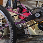
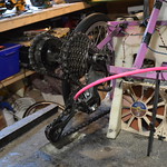
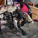
The use of a lay shaft in this system allows all of our gear ratios to end up very close together (see the ‘maths’ bit below), far more so than having put the gearing directly on the wheel end. It also allows us to use a derailleur the ‘correct’ way up while getting the advantages of a freewheeling hub (you can push the car backwards without worrying the chain will fall off!). If you look closely realistically you can see the rear end of a bike has been used, though the pedals/crankset have been replaced with the motor and the spokes/wheel have been replaced with the second chain to send drive to the driven wheel.
Parts of the system and tips on how we built them:
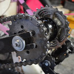
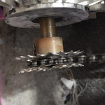
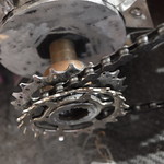
- The system starts at the motor output shaft. Here we have used a 10T gear that we managed to salvage from an old bicycle cassette I had lying around. It is important to remember that the chain on this side needs to be the correct ‘speed’ to match your cassette, in our case 9sp. By using an old cassette gear I know that it will be around the correct tooth width for 9sp. An old bicycle freehub is cut down to get the neccessary spline fitting to mesh with this gear which allows us to slide the gear off and put a different one on however, I am sure you can get away without this if you expect to change this gear size by simply welding the gear on to a coupler. There are 2 other larger gears shown which were a temporary (still going 1 season later!) measure to act as chain guides should the chain try and jump. This spline fitting is then fitted to the motor shaft via a steel coupler that we already had in stock, the two parts are welded together. Once I had access to a small lathe this part was later machined in to what you see in these pictures, this was simply to improve our accuracy.
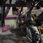
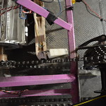
- A 9speed chain carrys power from the motor to the rear cassette, an off the shelf part that is mounted on to a disc braked mountain bike hub. The hub is the clever bit of this design. It gives the system a great way of achieving an idler shaft without the need to make your own bearing mounts etc. The freehub built in means that the ‘geared’ side of this setup doesn’t rotate when your car is freewheeling. You can see the slotted piece of steel we used to mount the hub in as well as the conventional bike ‘skewer’ that is still used to clamp the hub in place. This allows you to easily tension the ‘fixed gear’ side of the gearing, putting the correct amount of tension in to the chain on the left side of the car, the derailleur takes up the slack on the right had side chain.
- Over the other side of the idler shaft the disc brake mount is used to fix a 20tooth ‘single speed’ gear to. These are cheap but are made of very hard steel, very hard to drill! It can be done at home but I had a friend with a decent drill setup drill 6 holes in this gear so it would mount to ths standard disc brake bolt pattern. http://www.chainreactioncycles.com/gusset-1-er-single-speed-sprocket/rp-prod17778
- A single speed chain carries the power to the driven wheel. Our wheels have disc brake compatible hubs which means we have another opportunity to use this to pass torque in using this simple 6 bolt pattern. We wanted to be able to use normal bicycle chainrings which bolt up to a 5 bolt pattern PCD, this would allow us to change chainrings later if we wanted to change our ratio set. This part was a little hard for us to sort but would be easy with the correct access to laser cutting/decent fabrication. We ended up using a spider made from aluminium (link below), this was not the neatest solution as we had to open out the centre diameter to fit our axel as well as drill our own 6bolt pattern on to it. http://www.ebay.co.uk/itm/REDLINE-110-mm-BCD-SPIDER-for-one-peice-cranks-BMX-old-school-/371147285617?hash=item566a1a2471
- Gears are selected with an indexed shimano shifter (9speed). Currently we preference having ‘thumb’ shifters MTB style but may try some other options in the new season. With this setup I highly recommend getting the best gear cables you can afford (Jagwire seems quite good) as the length of inner/outer cable you need to run is quite long. Keep kinks to a minimum in order to reduce the friction, otherwise you may have trouble selecting gear.
The maths bit
This is a great exercise to go through in schools and excitingly when you do have a gearing system with telemetry (eChook Nano boards coming soon!) you will actually be able to check your calculations using the wheel speed and motor speed sensors to measure a ratio of gearing between the two!
The facts:
- Motor gear: 13tooth
- Lay shaft gear cassette: 14,15, 16, 17, 18, 19, 21, 23, 25
- Lay shaft fixed gear: 20tooth
- Wheel gear: 34tooth
The formula for working out your gears (with a lay shaft) in this setup works like this:
Overall Ratio = (Current Selected Lay shaft Gear / Motor Gear) * (Wheel Gear / Lay shaft Fixed Gear)
For our setup above this gives us a great set of ratios for us in F24+ on our car. The ratios we end up with start at 1.83 (very high wheel speed per motor RPM, a good high speed gear)) and end at 3.27 (very low wheel speed per motor RPM, a good pullaway and hill climbing gear), the difference between ratios is 0.13 for the single tooth steps on the chain ring and 0.26 for the 2 tooth steps. For our car this set of ratios offers a good range as well as resolution between gears.
We would suggest you have your team make a nice excel document with these calculations in (hopefully using our numbers you will get the same set of results we did!). Although these ratios work well with our car with our wheel sizes in F24+ they will not be optimum for other cars. An excel sheet will allow you to tweak things like the cassette you buy and the other gears in the setup in order to get the best result! It’s an exciting piece of maths to play around with and understand the impact that each gear has on your range (difference in ratio between top and bottom gear) and your resolution (differences between each gear you can select). Every gear in the system plays an important role in the result! You team probably has a good idea of the ratios that your car runs best at already from being on a fixed gear system, make sure these are included in your range of ratios available.

Leave a Reply